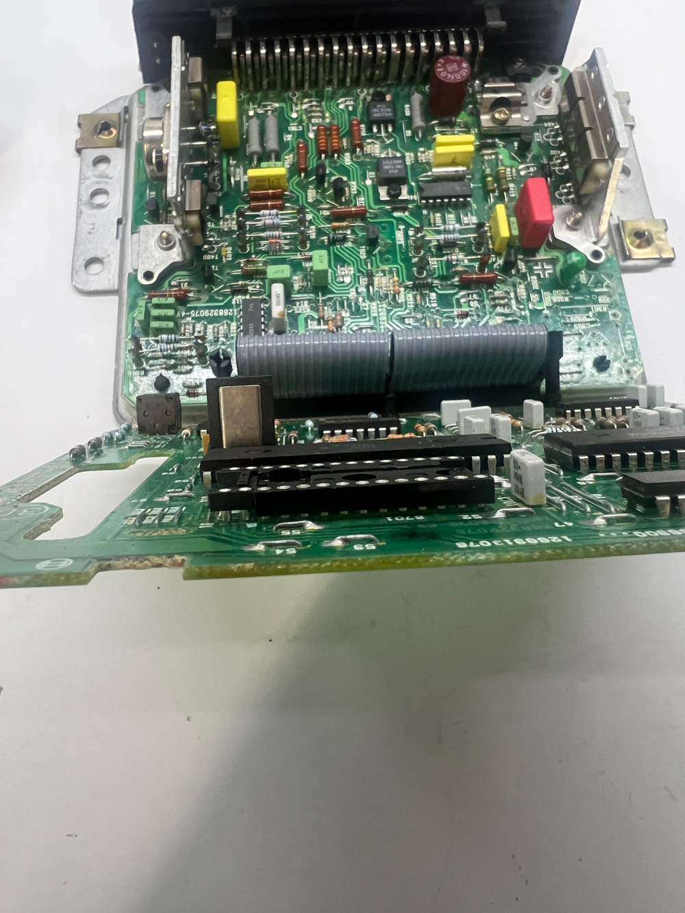
It's fairly well known that the early DMEs used a 24-pin EPROM and the later ones used a 28-Pin EPROM, and that it's fairly easy to convert from 24 to 28. See my video on doing that
here. To nudge the needle a little, I wanted to share my own guide to converting the DME, which allows you to use either chip.
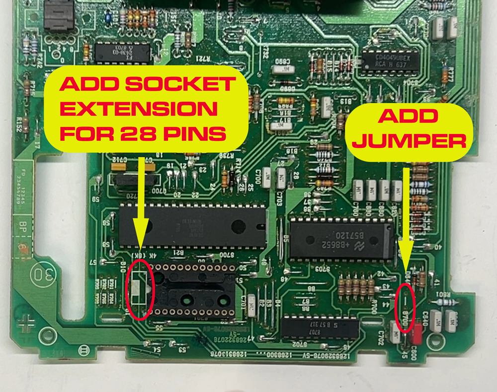
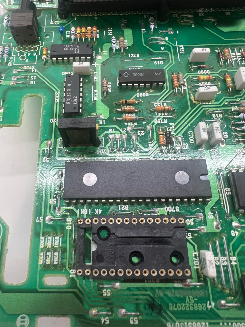
- CONVERSION-OVERVIEW.jpg (592.76 KiB) Viewed 301 times
To convert a 24-Pin DME to 28-pins, you just need to replace or extend the 24-pin socket to accommodate a 28-pin chip, and add a little jumper to the B700 space on the board to tell the DME you are using the bigger chip. That's pretty much it, since the DME board was set up from the beginning to use either chip.
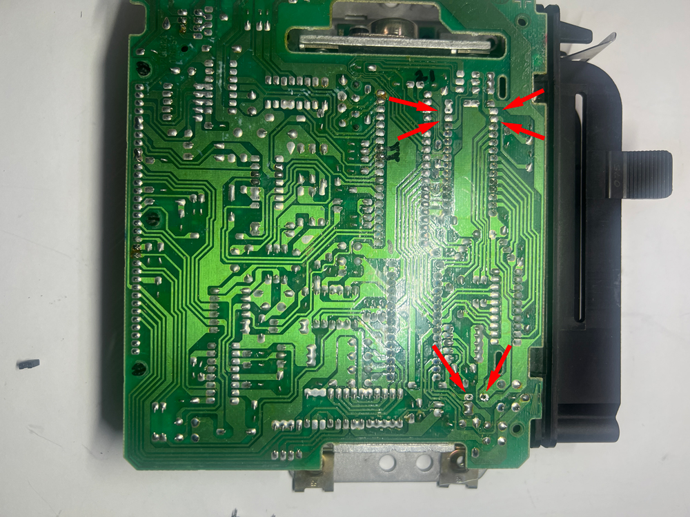
- desolder-point.jpg (652.86 KiB) Viewed 301 times
Before adding anything to those locations, you'll need to open up the holes in the circuit board, which are generally filled with solder. You can often just heat the solder to clear the holes, as the small amount of solder will often just wick back onto the pads. If that doesn't work, you can use a piece of stranded wire to wick up the solder, or a cheap solder sucker from Amazon, or a de-soldering gun. Google 'how to de-solder' for endless tips.
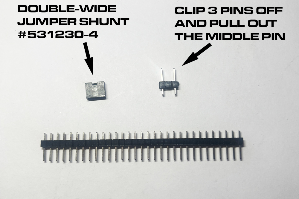
- double-wide-shunt.jpg (279.12 KiB) Viewed 301 times
The trick for making the DME compatible with either chip is not to solder a jumper wire into B700, but rather install a few header pins that can be shorted for the 28-pin EPROM, or not shorted for the 24-pin ERPOM. The B700 holes are too far apart for a standard (2.54mm) jumper shunt, but if you hunt around you CAN find a double-wide shunt that is perfect for the job. I use one by TE Connectivity, #531230-4. For the pins on the board, you can just get a standard header strip (2.54mm spacing), clip off three pins, and pull the middle pin out with needle nose pliers. Solder that into B700 and then you have your choice between using a 24 or 28-pin EPROM.
- shunt-for-28-pins.jpg (911.82 KiB) Viewed 301 times
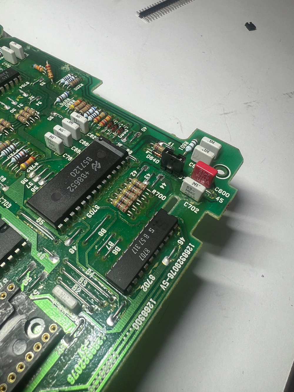
Here it is with the pins soldered in and the shunt installed on the pins, ready for a 28-pin EPROM. If you use a 24-pin EPROM, you can pull the shunt off the pins and just put it on one of the pins. That will store it for safe-keeping, without shorting the pins.
- extension.jpg (427.8 KiB) Viewed 301 times
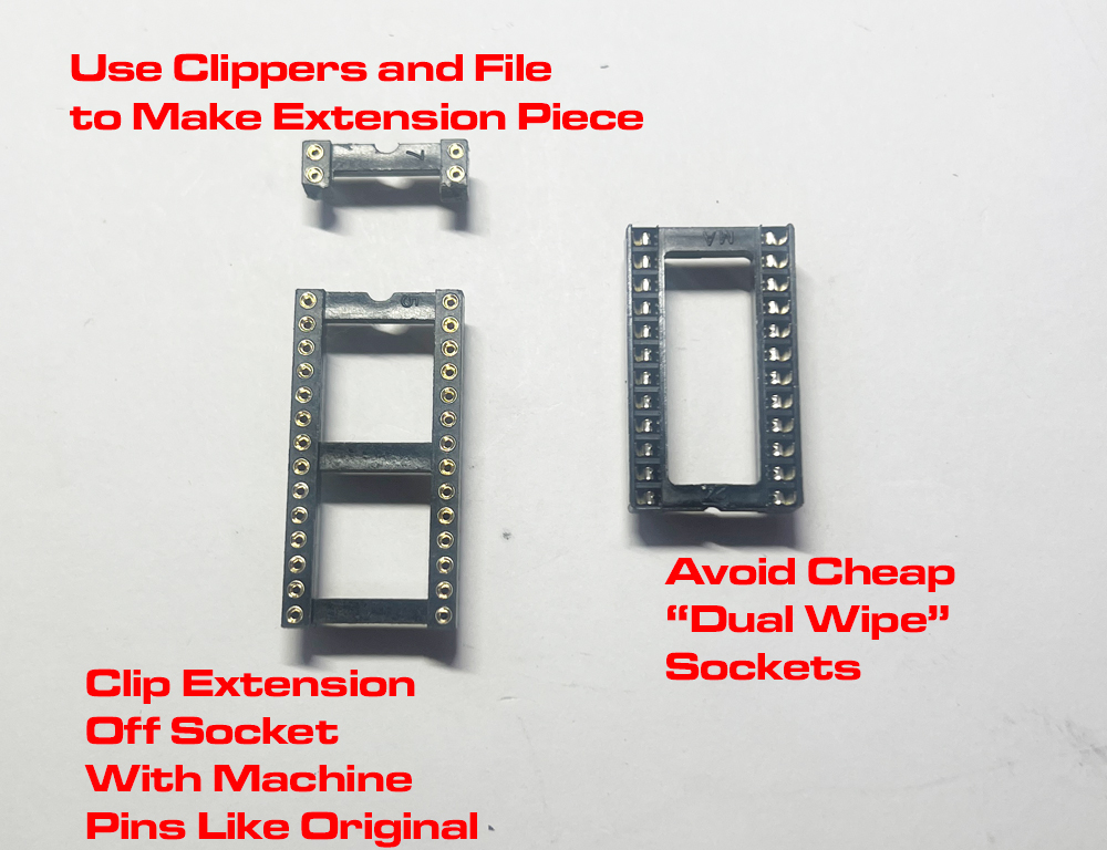
For the socket, you can cut the last two rows off a similar socket. Any socket with .6" width will work, since you only need the last two pins. Avoid cheap 'dual wipe' sockets and look for a socket with machine pins like the original.
- good-height-pins.jpg (763.75 KiB) Viewed 301 times
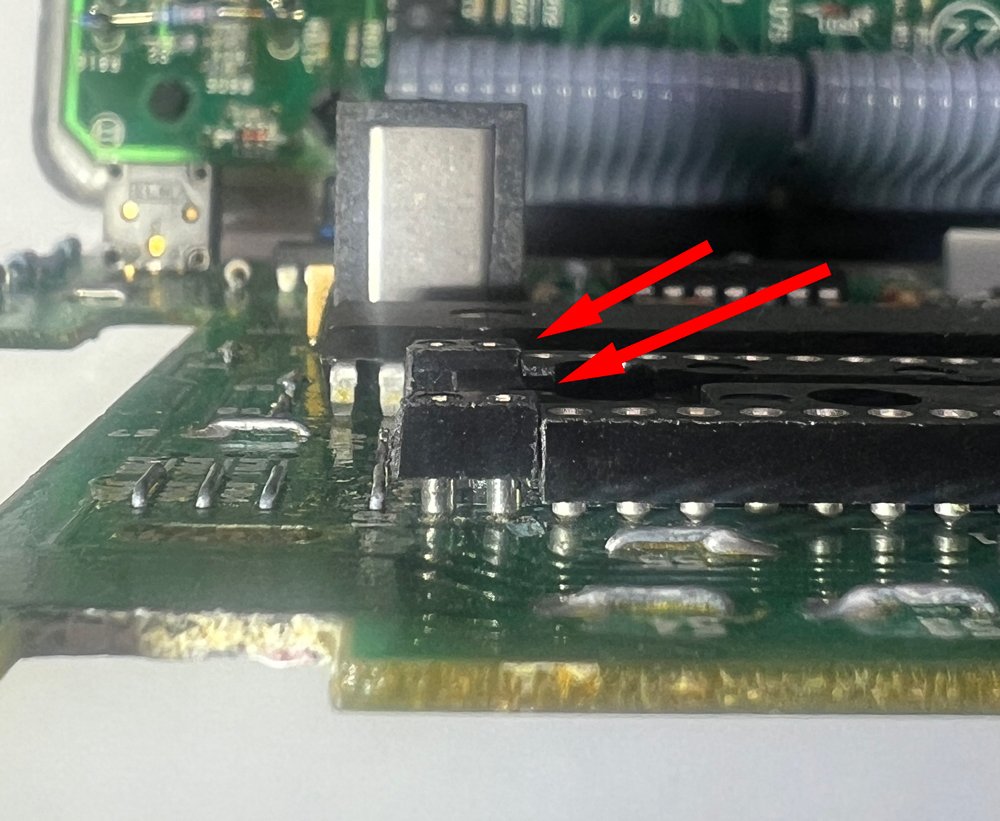
Note how this socket extension is just the right height to match the original. I got this socket at Anchor Electronics in Santa Clara, CA, but you may need to hunt around for a socket that's just the right height. This one came in a bag of ten, and even within the bag, they weren't all the same height.

- TOO-HIGH.jpg (476.83 KiB) Viewed 301 times
Here's one that was too high...
- TOO-LOW.jpg (464.91 KiB) Viewed 301 times
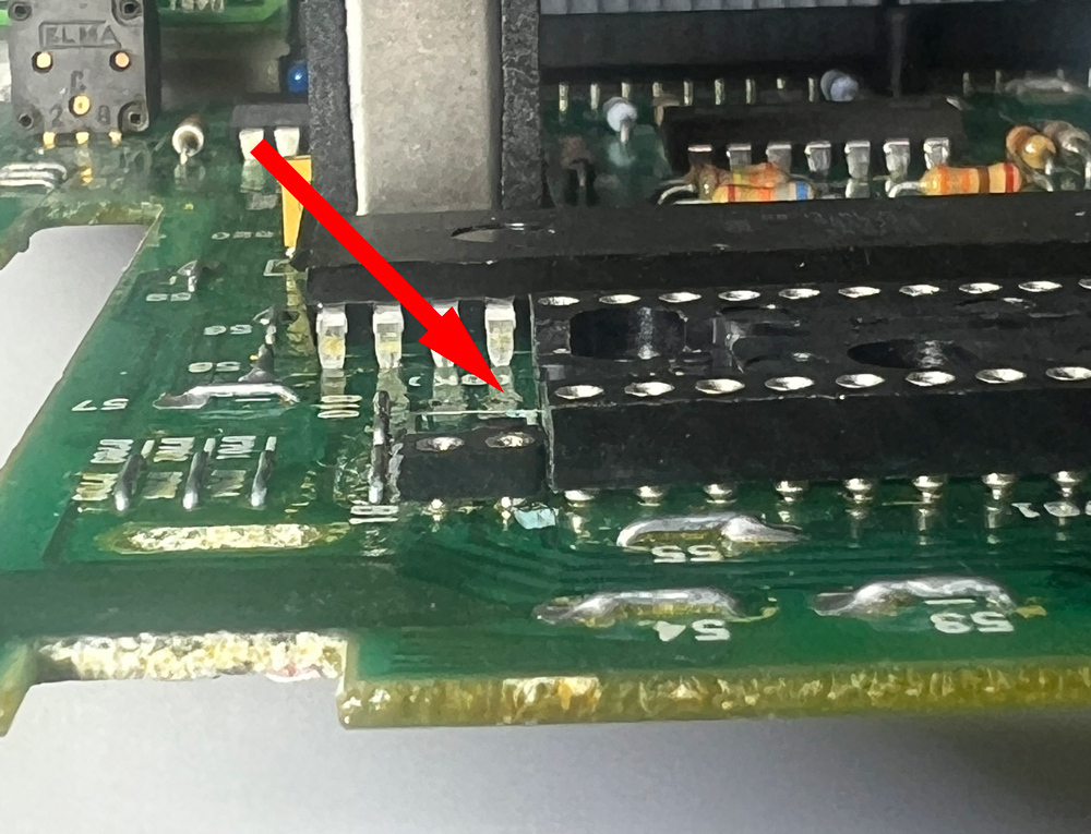
And one that's too low...
- EXTENSION-INSERTED.jpg (1.02 MiB) Viewed 282 times
And here is the extension inserted. With the jumper installed, it's ready for a 28-pin EPROM. Or remove the jumper, and use a 24-Pin EPROM in the original socket.