Page 1 of 2
1982 FoE Circuit Diagram
Posted: Sun Dec 15, 2024 8:23 pm
by Zirconocene
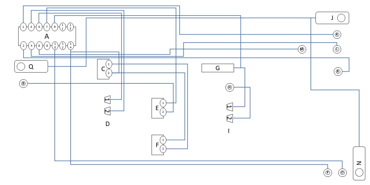
I've been working on making a front of engine harness for a friend (9zwei8, over on RL). He was kind enough to lend me his '82 harness for me to get all the relevant data. I'll make him a new one but, in the mean time, I thought I'd share the circuit diagram that I made to keep track of things.
Because I didn't take it off the car, and I don't have anything to look at earlier than my '90s, I can't quite identify what purpose the connectors serve. Nonetheless, hopefully this will be of some use to folks.
- 1982 FOE Harness.jpg (99.84 KiB) Viewed 2948 times
Cheers
Re: 1982 FoE Circuit Diagram
Posted: Sun Dec 15, 2024 8:29 pm
by Zirconocene
Here's an overview of the connections. I went through and tested them with a multimeter so I think this is a solid picture of how things are connected.
The old wires are a little tough to distinguish wrt the colors of the wires, and I'm bad at reading the older wiring diagrams, so please take the wire colors as my best guess.
ETA: One other note is that not all the connectors were present on the harness; some had fallen off due to corrosion. That's what the yellow box is for in the spreadsheet, where I know I don't know what that was. Others fell off during manipulation of the harness and I'm going from memory of what was there. There was some pretty bad oxidation throughout.

- Connections Spreadsheet.jpg (227.17 KiB) Viewed 2946 times
Cheers
Re: 1982 FoE Circuit Diagram
Posted: Mon Dec 16, 2024 8:08 am
by Tom
Great work and I'm sure it will be helpful for people for years to come

Can I ask what software tool you used to create it?
Re: 1982 FoE Circuit Diagram
Posted: Mon Dec 16, 2024 8:46 am
by Zirconocene
That was all drawn in PowerPoint. With it done I'm thinking about doing it in KiCad, which will make the line management on the screen easier. Not being a real CAD person, however, I don't know how universal that software package is; I just use it because it's free and I'm only an occasional tourist with those kinds of applications.
Cheers
Re: 1982 FoE Circuit Diagram
Posted: Mon Dec 16, 2024 10:18 am
by Tom
I'm rusty now, but have used Eagle in the past. They went upscale when Autocad bought them out, but KiCad appears to be a good alternative. They'd help, but not as visual as I'd like for harness designs. There are some uber expensive harness-specific design tools out there, but I've been on the hunt lately for a harness-specific tool for the casual harness maker (i.e., something without 'seat licenses' that cost more than my first car). Seems like there "should" be something out there...
Re: 1982 FoE Circuit Diagram
Posted: Mon Dec 16, 2024 10:34 am
by Zirconocene
If you find something, I'd love to know about it. I think I understand what you're getting at and, indeed, getting the full details of what it takes to build a harness is complicated. The wire lengths, runs, lengths to junctions, connectors, termination at connectors, etc., are all pretty important for building the things.
Cheers
Re: 1982 FoE Circuit Diagram
Posted: Mon Dec 16, 2024 12:24 pm
by four0four
KiCAD/EagleCAD aren't really suited for harnesses unfortunately. Usually that's the purview of the $$ tools like Tom said.
There's WireViz:
https://github.com/wireviz/WireViz
I've used it before but ran into some frustrating limitations that I can't quite call to mind at the moment.
Re: 1982 FoE Circuit Diagram
Posted: Tue Dec 17, 2024 1:26 pm
by Zirconocene
I've attached the KiCAD schematic to this post. As was mentioned, not really suited for this application but it has the ability to highlight all the connections in a circuit so it's useful to check the manual mapping I did.
Cheers
Re: 1982 FoE Circuit Diagram
Posted: Thu Dec 19, 2024 10:53 am
by dr bob
In my 'Archive Of Porsche Things' I have the circuit schedule for that KS-2 "front of engine" harness including the wire colors lengths and destination/clients. It's for a later car (S4+) so has a few connections the '82 won't. Like ABS and the IIRC the intake-flap solenoid. Porsche has been at least consistent with connections at that 14-pin main connector, and didn't swap anything as features were added in the later cars.
I think a copy of that same schedule was included in a thread about the top-of-engine harness, even though it wasn't relevant to the top harness.
If you are disassembling the '82 harness, it might be good to document the wire lengths, and maybe compare them with the later version.
I keep threatening to make a new KS-2 harness for my car, but haven't quite gotten around to buying the wire. If you are buying bulks of the multicolor wires I'd love to buy a kit from you. I can manage the fab part I think. LMK!
Re: 1982 FoE Circuit Diagram
Posted: Fri Dec 20, 2024 8:46 am
by Zirconocene
@dr bob : I sent you a PM, we can certainly do something on this together.
Cheers