Page 2 of 5
Re: Hello all and intro
Posted: Fri Feb 17, 2023 1:12 pm
by Drscottsmith
I misspoke....sorry! I have built an auxiliary fuse box that is driven from the ignition with through the DME relay (keeping that for that purpose. So I have a spot in the aux fuse box for the new cooling fan fuse. I would like to have outside temps as well.
I am having to build a little circuit to interface with and control the stock 3 wire Idle Control Valve as the Micro will not control that either. I'll go back to the manuals and see what I can find.
I appreciate you guys taking an interest in this and the help!!!
Re: Hello all and intro
Posted: Fri Feb 17, 2023 6:18 pm
by Drscottsmith
Here are a few idea pics….

- 9B1B65AF-AC25-497F-8BD9-BF27071AF5C0.jpeg (2.82 MiB) Viewed 798 times
This is a drawing I made to show the electronics and connections under the dash for the arduino and other items. Everything with a green slash would be inside a project box or old DME box near the microsquirt box.

- 264DF199-0DB9-47F8-982A-99566D443E32.jpeg (3.55 MiB) Viewed 798 times
The 16x2 would fit quite nicely here.
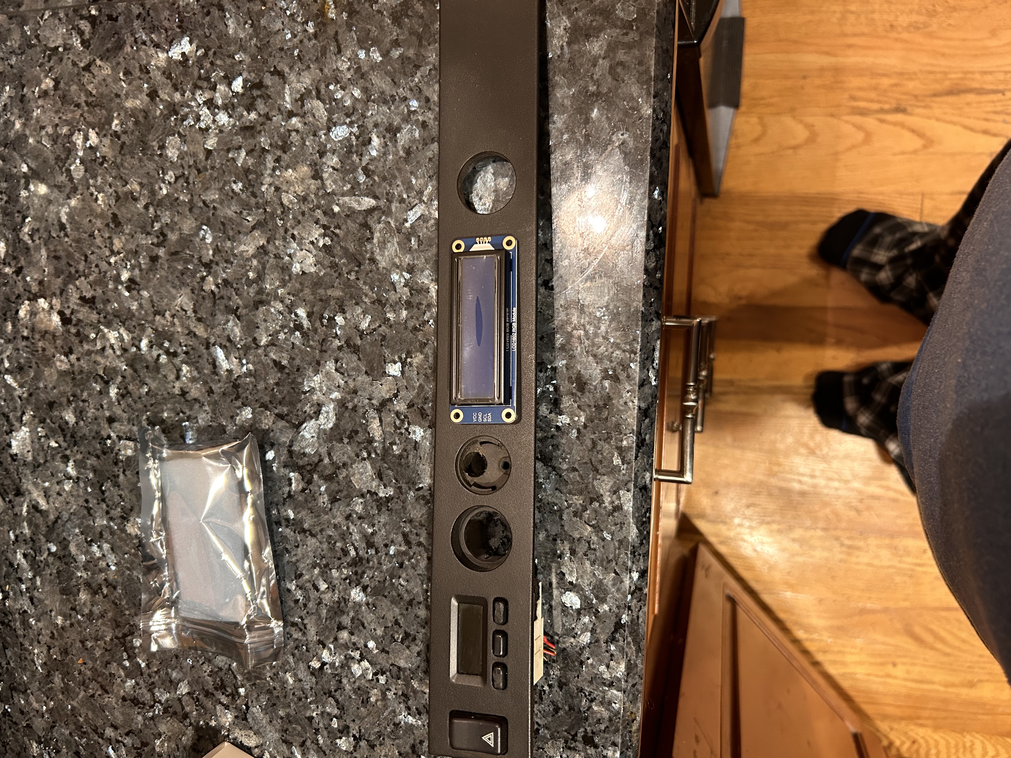
- 32C2149F-4083-4767-A3E6-32115C6D1652.jpeg (3.89 MiB) Viewed 798 times
Backside of the trim strip where 16x2 could possibly go. I really hate to hack up a trim piece though…

- CAE31A49-A99B-4C61-8C47-7CF5843DC573.jpeg (2.95 MiB) Viewed 798 times
My 16x2 is obviously quite a bit larger than the clock unfortunately. Perhaps a new 3d printed trim strip with the appropriate section removed?
Another idea might be a new strip with the clock out and 16x2 in its place and the lighter and air temp grill shifted to the right. Could also lose the lighter altogether as I will put a usb charger port in one of the unused console switch blanks.
Or find somewhere on the console for the 16x2
Re: Hello all and intro
Posted: Fri Feb 17, 2023 7:22 pm
by Tom
I'd be inclined to find a smaller LCD so you can retain the stock button locations to scroll through inputs. Just my two cents.
Why not drive the boost gauge directly from the mircosquirt variable voltage output? It would work the way you have it, but you would need a loop that constantly checks the MAP signal (off the CANBUS in your case) and updates the gauge output. Not a big deal if you aren't taxing the Arduino with other tasks, but you have the hardware to drive the boost gauge without taking any processing time from the Arduino. Either way, I'd probably use a Mega Arduino since it has significantly more processing capacity.
As for the CANBUS interface, I'm sure you know, but they make Arduino CANBUS 'shields' and even custom Arduinos with the CANBUS and Arduino all on one board.
Re: Hello all and intro
Posted: Sun Feb 19, 2023 4:29 pm
by Drscottsmith
Well a couple more updates. After going back through the Microsquirt manual, it appears that the only variable voltage output is the tach signal. The other outs (e.g. the wled, aled, etc are just on-off outputs for controlling relays and the like.
So the arduino is back to having three tasks to do. Still thinking about a screen location. Tom you up to printing a modified trim panel? I can send one to model.
Re: Hello all and intro
Posted: Sun Feb 19, 2023 5:48 pm
by Tom
Most tachometers (including the 944) run off a pulse corresponding to engine speed (like a fast EKG), so I'd be surprised if the tach output were an analog signal. If it really is, you'll need add'l hardware to run your tach.
Depending on what you are using it for, you can always use separate Arduinos for resource-hogging functions. The Arduino Nano is tiny and cheap. Chances are whatever LCD you use will effectively have its own Arduino built into it to drive the display....
I'm happy to print things if you send me .STL files. Just keep in mind size limitations. My highest resolution printer is the Form 3 resin printer -- it makes things that look nearly injection molded, but is limited to objects that fit in a 145mm x 145mm x 185mm box. My best traditional FDM printer is the new Bambu Lab X1 Carbon printer. It makes the best FDM prints I've ever seen. It's limits are 256mm x 256mm x 256mm. Lastly I still have my Lulzbot Taz 6, which makes very traditional looking FDM prints, but goes up to 280mm x 280mm x 250mm.
Re: Hello all and intro
Posted: Wed Feb 22, 2023 5:11 am
by Drscottsmith
OK so staring to think through the programming for the Arduino. Remember I need these things to happen:
1) Read CANBUS data from the Microsquirt module
2) Output a signal through PWM to control the Mazda Fan Module for the engine cooling fans
3) Output an analog out (0-5v) to control the Boost gauge on the dash
4) Output/control CANBUS information on the 16x2 display
5) Receive switch inputs through a selector switch
What Libraries for the Arduino will need to download and initialize? I have found an LCD library for the 16x2 and a CANBUS library.
Are there libraries for switch inputs and the variable DC output or is that just written in code?
Does PWM control output have a separate library or is that just coding as well?
Thanks as always.
Re: Hello all and intro
Posted: Wed Feb 22, 2023 8:19 am
by Tom
1) You might want to poke around on sparkfun.com. They offer powerful electronics to hobbyists that are supported with extensive hobby-level documentation and examples. This can be super helpful as you learn and infinitely more user-friendly than the data sheets that come with raw electronics components. See their CANBUS Arduino shield, for example. It does use a library, and they show great examples of how to use the hardware and software.
https://www.sparkfun.com/products/13262 ... LoQAvD_BwE
2) You can output a PWM signal straight from the Arduino, no library needed. I'd assume this would need to be part of a loop, or maybe a less frequent time-based interrupt, but checking temps will involve an ADC and then doing some kind of DAC output (which is slow on the Arduino) or raw PWM if you controller can handle that. My point is, you have quite a few things to accomplish for one relatively slow 8 bit controller. I'm sure it can be done (just look at what Bosch accomplished with the 8051 chip inside the DME!), but you will want to study up on how long the various tasks take, and give thought to efficiency, including the possibility of adding dedicated hardware to speed up bottlenecks on the Arduino.
3) You can do this with the analogWrite() built into the Arduino IDE. Keep in mind you also need to read the sensor to set the output, and the combo can consume processing power. See comment above. Unlike the fans, you need to sample the sensor and update the gauge many times per second for the gauge to move smoothly and without perceptible steps.
4). Once you get the data from the shield, driving an LCD is a common Arduino task with endless ways/libraries to accomplish it. Browse sparkfun for a display you like, and it will come with a hobby-level guide showing how to implement it. For example:
https://www.sparkfun.com/products/18160
5) Switches can tie in to basic digital inputs on the Arduino, no problem. You can poll them in a loop or tie them to interrupts. What are they for? You may need to denounce them depending on what they do.
PWM and analogWrite are standard parts of the Arduino IDE.
Re: Hello all and intro
Posted: Wed Feb 22, 2023 8:38 am
by Drscottsmith
Thanks Tom - makes sense. I want to get a bench setup going to see exactly how this is going to work with everything and check the processing power as you describe - for simultaneous loops that will be running as long as the car is.
Re: Hello all and intro
Posted: Wed Feb 22, 2023 8:49 am
by Tom
Drscottsmith wrote: Wed Feb 22, 2023 8:38 am
Thanks Tom - makes sense. I want to get a bench setup going to see exactly how this is going to work with everything and check the processing power as you describe - for simultaneous loops that will be running as long as the car is.
That's what I generally do. Take it one function at a time. Get the LCD going, then add a button or two to control it, then learn to read a sensor, etc. For those drawn to this kind of thing, it can be a fun and rewarding way to spend time. Once you get the hang of the Arduino (or any of the hobby-level microprocessors available these days), the possibilities become endless. The speeduino is an entire engine management system based on the Arduino.
Re: Hello all and intro
Posted: Wed Feb 22, 2023 9:02 am
by blueline
Tom, Drscottsmith, et al - I don't know squat about any of this discussion but it's impressive to read anyway. I'm trying to look up a few things in a mostly vain attempt to learn a bit, all of which will probably be immediately forgotten.

Best of luck with the endeavors!